


Views: 0 Author: Site Editor Publish Time: 2026-07-30 Origin: Site


As energy costs escalate and building efficiency mandates become stricter, precise measurement of thermal energy transfer is no longer optional for modern facilities. Facility managers and property developers face challenges with inaccurate tenant billing, inefficient hydronic HVAC systems, and a lack of verifiable data for ESG reporting. Relying on estimates or outdated mechanical measurement leads to revenue leakage and operational blind spots. Understanding the exact mechanics of a Heat Meter—and the technical trade-offs between different metering technologies—is critical for specifying a system that delivers long-term accuracy, seamless Building Management System (BMS) integration, and verifiable ROI.
A heat meter calculates thermal energy consumption by measuring two distinct variables in a closed-loop system: the flow rate of the heat transfer fluid and the temperature differential between the supply and return lines.
While mechanical meters offer a lower barrier to entry, the ultrasonic heat meter has become the industry standard for commercial applications due to its lack of moving parts and sustained accuracy over time.
Successful implementation requires evaluating meters based on EN 1434 compliance, communication protocol compatibility (e.g., BACnet, M-Bus), and specific pipe sizing constraints.
Proper installation—including adherence to straight pipe run requirements and correct sensor placement—is critical to mitigating adoption risks and preventing data degradation.
A thermal energy meter acts as an HVAC field device. It quantifies the thermal energy provided by a central heating or cooling source. You install these devices to monitor specific buildings, zones, or individual apartments. They eliminate guesswork from energy consumption tracking by providing hard data on exactly how much thermal energy a specific circuit extracts from the primary loop.
Industry professionals use different terms based on geographic location and application. Understanding these variations helps when reading specification sheets or communicating with international vendors.
BTU Meter: North American commercial HVAC systems primarily use this term. It measures energy in British Thermal Units. You will often see this terminology in chilled water applications for large commercial office buildings.
Thermal Energy Meter: This globally recognized term dominates European district heating networks. It aligns closely under EN 1434 compliance frameworks and is the standard terminology used in legal metrology documents.
Every metering system relies on three distinct physical components working together. If any one of these components fails or falls out of calibration, the entire energy calculation becomes invalid.
Component | Function | Field Application and Technical Details |
|---|---|---|
Flow Sensor (Volume Measuring Device) | Captures the volume of fluid passing through the system. | Installed directly in the pipe to measure velocity and volume. Can be mechanical (impeller) or static (ultrasonic/electromagnetic). Must be sized according to nominal flow rate, not pipe diameter. |
Temperature Sensors (Thermistor/RTD pair) | Measures the exact temperature drop or rise across the load. | One PT100 or PT500 sensor sits on the supply line, the other on the return line. They must be a matched pair to ensure the delta-T calculation is not skewed by individual sensor drift. |
Calculator/Integrator | Computes the thermal energy transfer using thermodynamic formulas. | A microprocessor receiving pulse or digital data from the flow and temperature sensors. It houses the battery, communication modules, and the display screen. |
The integrator relies on a strict thermodynamic calculation. Thermal Energy equals Flow Rate multiplied by the Temperature Difference (ΔT). The equation also factors in the Specific Heat Capacity and the density of the fluid. The microprocessor constantly runs this calculation to output accurate energy consumption data. Because fluid density and specific heat change depending on the temperature, the calculator must dynamically adjust its internal k-factor based on the real-time temperature readings from the supply and return sensors.
These devices operate exclusively within closed heating and cooling circuits. Common applications include central boiler systems, chilled water systems, and heat pumps. The fluid circulates continuously. The meter measures the energy extracted from or added to this closed loop without consuming the fluid itself.
Capturing the delta-T (ΔT) is the most critical function. The meter reads the temperature of the fluid entering the zone. It then reads the temperature of the fluid leaving the zone. By comparing these two values, the device differentiates between energy consumed by the building and energy returning to the central plant. For example, if water enters a radiator circuit at 80°C and returns at 60°C, the 20°C delta-T represents the thermal energy transferred into the room.
Modern communal schemes rely heavily on the Heat Interface Unit (HIU). The HIU separates the central network from the local apartment system using plate heat exchangers. The meter integrates directly within or alongside the HIU on the primary circuit side. This setup ensures accurate, property-level consumption tracking from a shared centralized plant. It allows network operators to bill individual tenants based on their exact usage rather than a flat floor-space ratio.
Many modern facilities utilize two-pipe and four-pipe hydronic systems. These systems switch between heating and cooling depending on the season. Combined meters handle this transition seamlessly. The integrator uses logic to automatically switch calculation modes. If the supply temperature exceeds the return temperature, it logs heating data. If the supply temperature falls below the return temperature, it logs cooling data. It stores these values in separate registries, allowing facility managers to track heating and cooling efficiency independently.
Raw sensor data holds little value on its own. The integrator translates these electrical signals into actionable billing metrics. Facility managers read these outputs in kWh, MWh, Joules, or BTUs. This translated data feeds directly into performance dashboards via communication protocols, enabling real-time monitoring of plant efficiency and tenant consumption.
Selecting the right technology depends entirely on your system demands. Different mechanisms offer distinct advantages and drawbacks. Specifying the wrong flow measurement technology leads to premature failure and inaccurate data.
These devices utilize an impeller, turbine, or Woltman wheel to measure flow. The physical movement of the fluid turns the mechanism, generating a pulse for every rotation.
Pros: They offer a lower initial capital expenditure. They work well for clean, low-demand residential systems where flow rates remain relatively constant.
Cons: They remain highly susceptible to mechanical wear and tear. Moving parts degrade over time. This degradation leads to pressure drops, scale buildup, and a progressive loss of measurement accuracy. A worn impeller will under-record flow, leading to lost revenue for the building owner.
An Ultrasonic Heat Meter uses transit-time technology. It sends acoustic signals upstream and downstream. This measures fluid velocity without obstructing the flow path. The time difference between the upstream and downstream signals is directly proportional to the fluid velocity.
Pros: They feature no moving parts. They resist debris effectively. You experience zero mechanical wear. They maintain high accuracy over a 10-15 year lifecycle and cause negligible pressure drop, which saves on pumping energy.
Cons: They require a higher initial procurement cost. They also demand specific installation conditions to prevent air bubbles from disrupting the acoustic signal, as air pockets scatter the ultrasonic waves.
These units use Faraday’s Law of Induction. They measure flow velocity in conductive fluids using magnetic fields. As the conductive fluid passes through the magnetic field, it generates a voltage proportional to the velocity.
Engineers typically reserve these for heavy industrial applications. They excel in large-scale district heating networks or dirty fluid loops. In these harsh environments, ultrasonic paths might face severe signal attenuation from heavy particulate matter. However, they require the fluid to have a minimum electrical conductivity, meaning they cannot be used with demineralized water.
You cannot select a meter based on pipe size alone. Proper specification requires a deep understanding of system dynamics, fluid properties, and compliance standards.
Legal, billing-grade applications demand strict adherence to standards. EN 1434 and Measuring Instruments Directive (MID) approval are non-negotiable for any system where money changes hands based on the meter reading. Class 2 accuracy ratings provide tighter tolerances than Class 3. Selecting a Class 2 device directly impacts revenue recovery and minimizes tenant billing disputes.
EN 1434 Accuracy Class | Typical Application | Tolerance Characteristics |
|---|---|---|
Class 1 | Laboratory and highly sensitive industrial processes. | Extremely tight tolerances. Rarely used in standard commercial HVAC due to expense. |
Class 2 | Commercial billing, district heating, tenant submetering. | The industry standard for revenue-grade metering. Balances high accuracy with practical field deployment. |
Class 3 | Internal monitoring, residential check-metering. | Wider tolerance bands. Not recommended for legal billing applications where disputes may arise. |
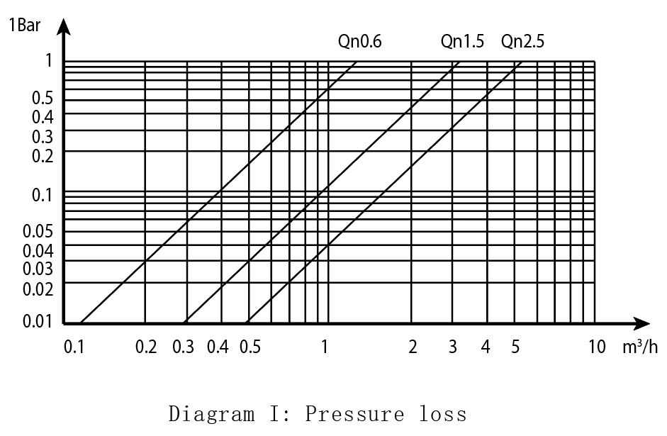
Never match the meter simply to the existing pipe diameter. You must match the meter's nominal flow rate (qp) to the system's actual design flow. Oversized meters fail to read low flow rates accurately, missing energy consumption during low-load periods. You must also evaluate pressure drop implications. High pressure drops force circulation pumps to consume more energy to maintain system flow, negating the efficiency gains you are trying to measure.
Water-glycol mixtures require specialized integrator calibration. Standard water calibrations produce significant measurement errors in glycol systems. Antifreeze alters both the density and the specific heat capacity of the fluid. You must program the integrator for the exact fluid composition (e.g., 30% Propylene Glycol). Failure to do so can result in measurement errors exceeding 15%.
A meter must seamlessly pass data to a BMS, SCADA, or automated billing software. You must evaluate your protocol options carefully based on the building's infrastructure.
Wired Protocols: M-Bus, Modbus, and BACnet offer robust, continuous data transmission. M-Bus is specifically designed for metering and allows for long cable runs with multiple devices daisy-chained together.
Wireless Protocols: Wireless M-Bus, LoRaWAN, and NB-IoT reduce installation labor but require careful network planning to ensure signal penetration through concrete floors and mechanical room walls.
Even the best hardware fails if installed incorrectly. Field execution dictates long-term performance. Contractors must follow strict mechanical guidelines during installation.
You must adhere to upstream and downstream straight pipe runs. Common rules include 5D/3D or 10D/5D configurations (where D equals the pipe diameter). These straight sections eliminate turbulence caused by elbows, valves, or pumps. They ensure laminar flow across the sensors. Laminar flow remains absolutely critical for accurate ultrasonic readings, as turbulent flow profiles distort the acoustic transit time.
Magnetite and scale build-up pose severe risks to hydronic systems. Poor water quality destroys mechanical meters rapidly by jamming the impellers. While ultrasonic models mitigate this risk by removing moving parts, they still require protection. Heavy magnetite sludge can coat the internal reflectors of an ultrasonic meter, weakening the signal. You must implement proper system flushing, dirt separation, and magnetic strainers during commissioning.
Asymmetrical temperature sensor installation ruins data accuracy. You must ensure matched immersion depths for both supply and return sensors. If one sensor sits in the center of the flow stream and the other sits near the pipe wall, the delta-T calculation will be artificially skewed. Furthermore, you must establish lifecycle calibration schedules. Regular calibration maintains legal compliance and trust in the data.
Deploying precise measurement devices directly impacts facility profitability and operational compliance. It transforms a mechanical room from a black box into a transparent, data-driven asset.
Accurate metering eliminates flat-rate billing disputes. You provide transparent, consumption-based data. This verifiable data stands up to regulatory scrutiny and tenant audits. Tenants only pay for the energy they actually consume, which incentivizes energy conservation behavior at the user level.
Delta-T data helps identify "low delta-T syndrome," a common issue where water pumps through the building too quickly without transferring its thermal energy. You can use this information to optimize variable-speed pump operations. Correcting these issues improves overall chiller and boiler plant efficiency, reducing primary fuel consumption.
Modern mandates require hard data. Accurate meters provide verifiable metrics for energy audits. You need this data for carbon footprint calculations and green building certifications like LEED and BREEAM. Without revenue-grade metering, ESG reports rely on estimates, which fail modern auditing standards.
Accurate thermal energy measurement forms the foundation of modern energy management. While mechanical meters serve basic, low-budget needs, ultrasonic technology provides the long-term reliability and data integrity required for commercial and industrial applications. Base your final selection on legal compliance requirements and integration capabilities with your existing BMS infrastructure. Factor in maintenance, recalibration, and expected lifespan when making your choice.
Audit your current hydronic system's design flow rates to properly size new meters based on nominal flow, not pipe diameter.
Identify the exact fluid composition in your loops to ensure correct specific heat calibration within the integrator.
Consult with a metering specialist to verify straight pipe run availability at proposed installation points to guarantee laminar flow.
Request technical data sheets for shortlisted devices to confirm BMS protocol compatibility and integration requirements.
A: A water meter only measures the volume of fluid passing through a pipe. A heat meter measures both the fluid volume and the temperature differential between supply and return lines to calculate actual thermal energy transfer.
A: They typically meet EN 1434 Class 2 standards. Because they lack moving parts, they maintain high accuracy (usually within ±2-3%) consistently over their entire 10 to 15-year lifespan without mechanical degradation.
A: You can install them on either the return line or the supply line. However, you must configure the integrator for the specific installation point because fluid density changes based on temperature.
A: Yes. Combined heating and cooling meters automatically switch calculation modes based on the temperature differential. They store the heating and cooling data in separate registers for accurate billing.
A: Industry standards typically require calibration every 5 years to maintain legal billing compliance. However, ultrasonic models often maintain their physical measurement accuracy much longer due to zero mechanical wear.
A: High-quality commercial meters generally last 10 to 15 years. The lifespan is most often limited by the battery life of the integrator or the communication module, rather than sensor failure.

