


Views: 0 Author: Site Editor Publish Time: 2026-07-30 Origin: Site


In commercial real estate, district heating networks, and industrial facilities, precise energy allocation is a baseline requirement for cost recovery and ESG reporting. Relying on estimates or outdated measurement techniques leads to inaccurate tenant billing, undetected system inefficiencies, and non-compliance with stringent energy regulations. Facility managers and engineers need verifiable, auditable data to optimize hydronic systems. Understanding the exact mechanical and thermodynamic processes a Heat Meter uses to calculate energy consumption is the first step in specifying the correct hardware. This guide breaks down the operational mechanics, technology variations, and critical evaluation criteria required to select a reliable metering solution.
Thermodynamic Foundation: Heat meters calculate energy usage using the formula Q = m × c × ΔT, relying on synchronized data from flow rates and temperature differentials.
Technology Trade-offs: The choice between mechanical and ultrasonic flow sensors dictates long-term accuracy and maintenance frequency.
Integration is Critical: A thermal energy meter is only as effective as its ability to transmit data; compatibility with Building Management Systems (BMS) via protocols like BACnet or Modbus is essential for automated billing.
Compliance and Standards: Selecting meters that adhere to international standards (e.g., EN 1434, MID) ensures legal defensibility for tenant billing and regulatory audits.
To evaluate a meter's accuracy, buyers must first understand the fundamental physics it relies upon. The device converts physical fluid properties into digital energy data through continuous mathematical integration. Field engineers know that a meter is only as good as the raw data it collects from the pipe.
Every thermal calculation relies on a standard thermodynamic formula. The variable Q represents the total thermal energy consumed. The variable m stands for the mass flow rate of the heat transfer fluid. The variable c is the specific heat capacity of that fluid. Finally, ΔT represents the temperature difference between the supply and return lines.
The meter's internal calculator continuously integrates these three variables over time. It samples flow and temperature data at rapid intervals, often multiple times per second. The microprocessor multiplies these real-time values to output cumulative energy consumption. This final figure typically displays in kilowatt-hours (kWh), megawatt-hours (MWh), or British Thermal Units (BTUs). In large commercial setups, you will often see these values mapped directly to a central dashboard for daily monitoring.
A complete metering assembly requires three distinct hardware components working in unison. If one component fails or drifts out of calibration, the entire energy calculation becomes invalid.
Flow Sensor: This component measures the volume or mass of the fluid moving through the closed heating circuit. Installers mount it directly inline with the piping network, usually on the return line where temperatures are lower to protect the electronics.
Temperature Sensor Pair: These are matched thermistors or Resistance Temperature Detectors (RTDs). Installers place one sensor in the outflow (supply) pipe and the other in the inflow (return) pipe. They must sit in thermowells that penetrate deep enough to read the core fluid temperature.
Integrator/Calculator: This microprocessor unit receives electrical signals from the sensors. It applies the specific heat coefficient of the fluid, accounts for density changes at different temperatures, and computes the final energy value.
Standard thermal energy meters assume a closed hydronic loop. This means the fluid volume entering the system equals the fluid volume exiting it. The hardware measures flow at a single point, relying on this closed-loop principle to calculate total mass transfer. If a system has a leak, the energy calculation will skew because the mass flow rate is no longer consistent across the supply and return lines.
Fluid properties heavily influence measurement accuracy. Glycol mixtures or alternative heat transfer fluids alter the specific heat capacity (c) constant. Water has a different thermal capacity than a 30% propylene glycol mix. Modern calculators must be programmed for these fluid-specific properties. Failing to input the correct fluid type causes massive accuracy drift, rendering the billing data useless. We often see contractors forget to update the fluid parameters after a system flush and glycol refill, leading to months of inaccurate tenant bills.
The mechanism used to measure flow is the primary differentiator among meter models. Each technology presents specific operational trade-offs regarding accuracy, maintenance, and fluid compatibility. Selecting the wrong flow sensor type for your specific water quality will guarantee premature failure.
Mechanical meters utilize a physical turbine or impeller placed directly in the fluid stream. As water pushes past the blades, the impeller spins. The rotation speed correlates directly to the flow rate. A magnetic pickup or optical sensor counts these rotations to determine volume.
These devices perform well in clean, standardized water systems. However, the moving parts are susceptible to wear. Scaling and debris accumulation on the impeller blades lead to accuracy degradation over time. Facility teams must schedule regular maintenance to clean strainers and verify mechanical integrity. If you open a mechanical meter after five years in a poorly treated hydronic system, you will likely find the impeller coated in black magnetite sludge.
Ultrasonic meters measure the transit time of high-frequency sound waves. Transducers send acoustic signals with and against the fluid flow. Sound travels faster when moving with the current and slower when moving against it. The microprocessor calculates the time difference to determine precise fluid velocity.
This technology features no moving parts. The design results in zero mechanical wear, minimal pressure drop, and sustained accuracy over a longer lifespan. Ultrasonic units are highly effective for district heating networks. They can be sensitive to high levels of entrained air or heavy particulate matter, which scatter the acoustic signals. Installers must ensure proper air elimination devices are active in the mechanical room before commissioning ultrasonic units.
Electromagnetic meters use Faraday’s Law of Induction. They measure the voltage generated by a conductive fluid passing through a magnetic field. The induced voltage is directly proportional to the fluid velocity.
These units are ideal for highly corrosive or heavily contaminated industrial fluids. Mechanical and ultrasonic meters would fail in these harsh environments. While highly accurate, electromagnetic meters are typically overkill for standard commercial HVAC applications due to their complexity and power requirements. They require a dedicated power drop and strict grounding protocols to function correctly.
Technology | Mechanism | Primary Advantage | Primary Limitation |
|---|---|---|---|
Mechanical | Turbine/Impeller | Simple operation and repair | Moving parts wear out over time |
Ultrasonic | Acoustic transit time | No moving parts, sustained accuracy | Sensitive to air bubbles in fluid |
Electromagnetic | Magnetic induction | Handles highly contaminated fluids | Requires conductive fluid, complex setup |
The accuracy of the temperature differential (ΔT) calculation is highly sensitive. Even a 0.1°C error can significantly skew billing data, especially in systems operating with low temperature spreads. You cannot compromise on sensor quality.
Precise sensor placement is mandatory. Installers must place one sensor in the hot supply line and one in the cooler return line. The physical installation dictates the data quality. Thermal stratification within the pipe can cause inaccurate readings if the sensor probe does not reach the center of the fluid stream. Proper immersion depths within the pipe are required to capture the true average temperature of the fluid. We recommend using thermowells that extend at least one-third of the way into the pipe diameter.
Temperature sensors must be factory-calibrated as matched pairs. Manufacturers test these probes together to ensure their resistance curves align perfectly across the entire operating temperature range. This pairing eliminates baseline offset errors.
Replacing a single sensor instead of the matched pair is a major compliance risk. Mixing unmatched sensors invalidates the meter's overall accuracy class. It also voids legal compliance certifications required for financial billing. Always replace temperature sensors as a complete, factory-calibrated set. Never splice sensor cables to extend their length, as the added electrical resistance will destroy the calibration.
Modern smart meters handle bidirectional or negative delta-T calculations. Commercial buildings often use the same hydronic piping for both heating and cooling. The meter must differentiate between these modes to allocate energy correctly.
The calculator dynamically switches its specific heat capacity algorithms when transitioning between seasons. Winter heating might utilize 80°C water, while summer cooling relies on 7°C chilled water. The density and thermal capacity of water change drastically between these extremes. Advanced calculators detect the temperature shift and apply the correct thermodynamic tables automatically. This prevents the facility manager from having to manually reprogram the meters twice a year.
A standalone meter requires manual reading, which is prone to human error. For enterprise scalability, a Thermal Energy Meter must integrate seamlessly into existing network architectures. Data silos defeat the purpose of advanced metering.
Hardware specification must align with the building's digital infrastructure. Legacy systems often rely on simple pulse outputs, which only transmit basic volume data. Modern facilities require rich data streams to diagnose system health.
M-Bus: The standard protocol for European metering applications, designed specifically for reading utility meters over long distances using a simple two-wire bus.
Modbus RTU/TCP: A robust, widely adopted industrial protocol that allows for deep data extraction and integration with PLCs. It requires strict attention to baud rates and parity settings during setup.
BACnet: The dominant standard for North American HVAC and Building Management Systems (BMS), ensuring seamless interoperability between different equipment brands.
Specifying the correct communication module during procurement is critical. Retrofitting communication cards in the field is time-consuming and introduces unnecessary integration risks. Always verify the exact protocol and network topology with the controls contractor before ordering hardware.
Integrated meters enable real-time system visibility. Facility managers can monitor instantaneous flow rates, track thermal degradation, and identify stuck valves. Rapid temperature drops often indicate system leaks or failing insulation. Having this data on a central dashboard allows maintenance teams to dispatch technicians before tenants even notice a drop in comfort.
Networked meters facilitate automated, legally compliant tenant billing. Software platforms pull data directly from the integrator via BACnet or M-Bus. This eliminates manual meter reading routes, reduces administrative overhead, and provides tenants with transparent, verifiable usage reports. Automated systems also flag anomalous consumption spikes, protecting both the landlord and the tenant from surprise bills.
Evaluating hardware requires looking beyond basic spec sheets. Engineers must assess how the physical meter impacts the broader mechanical facility. A meter that looks great on paper might cause massive hydraulic issues if applied incorrectly.
Application location dictates the required hardware grade. Boundary or utility-grade metering involves high-flow, heavy-duty master meters. These sit at the building's main mechanical point of entry for district energy custody transfer. They require maximum legal accuracy, ruggedized housings, and redundant communication outputs. Flanged connections are standard here to handle high system pressures.
Tenant sub-metering involves scaled-down inline meters. Installers place these on localized manifold branches to divide costs among individual commercial units or apartments. Sub-meters prioritize compact form factors, wireless communication capabilities, and ease of installation in tight mechanical closets. Threaded connections are typical for these smaller pipe diameters.
The EN 1434 standard defines strict accuracy classes for thermal metering. Class 1 offers the highest precision, typically reserved for large-scale custody transfer. Class 2 is the industry standard for commercial sub-metering and tenant billing. Class 3 provides basic monitoring accuracy for internal energy management where financial transactions are not involved.
Applications involving financial transactions require specific legal approvals. In Europe, meters must carry MID (Measuring Instruments Directive) certification. In North America, NTEP certification ensures the device meets legal metrology standards. Using uncertified meters for tenant billing exposes property owners to significant legal liability and potential lawsuits from tenants disputing their utility charges.
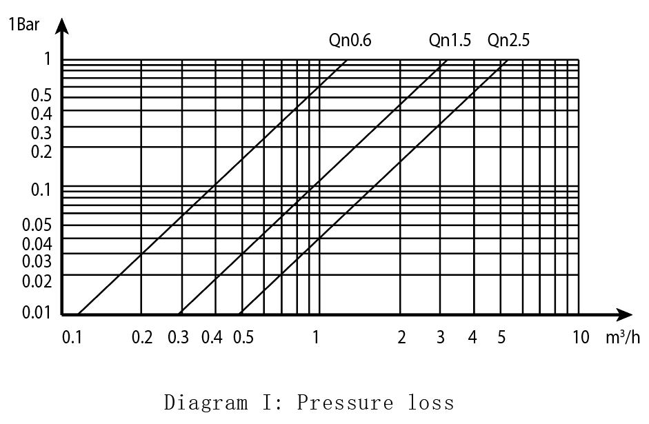
The physical design of the flow sensor introduces flow resistance. Mechanical turbines obstruct the fluid path, creating a measurable pressure drop across the device. Ultrasonic meters feature smooth, open flow tubes, resulting in negligible resistance.
Excessive pressure drop forces circulation pumps to work harder to maintain system flow. This inadvertently increases electrical energy consumption. Engineers must calculate the pressure drop of the selected meter and ensure it does not offset the thermal efficiency gains the facility aims to achieve. Always check the manufacturer's Cv rating before approving a meter for a low-head pumping system.
Even the most accurate measurement device will fail if installed incorrectly. Field conditions rarely match laboratory testing environments. You must anticipate mechanical room constraints and water quality issues during the design phase.
Flow turbulence distorts volume readings. Elbows, control valves, or circulation pumps located immediately upstream of the meter create chaotic fluid dynamics. The flow sensor cannot accurately measure turbulent water. If you install a meter right after a 90-degree elbow, the flow profile will be skewed to one side of the pipe, causing massive reading errors.
Installers must adhere strictly to manufacturer requirements for straight pipe runs. A standard rule requires a straight pipe length equal to 5 to 10 times the pipe diameter upstream of the flow sensor. Downstream requirements typically demand 3 to 5 times the pipe diameter. These straight runs allow the fluid profile to stabilize before passing through the measurement zone. If space is tight, you must select a meter specifically designed for zero straight-run requirements.
Hydronic systems often contain magnetite, pipe scale, and construction debris. These contaminants foul mechanical impellers and coat ultrasonic reflectors. Poor water quality is the leading cause of premature meter failure. We frequently see brand new meters destroyed within weeks because the piping network was not flushed properly after construction.
Implement proper water treatment protocols before installing sensitive measurement equipment. Install Y-strainers immediately upstream of mechanical meters to catch large debris. Establish a scheduled recalibration cycle aligned with local regulatory requirements to ensure long-term billing accuracy. Regular side-stream filtration will also protect the meter sensors from suspended solids over the life of the building.
Selecting and implementing the right measurement hardware secures revenue and optimizes system performance. Follow these actionable steps to ensure successful deployment:
Audit your hydronic system fluid to confirm specific heat capacity requirements before procurement.
Verify the exact communication protocol required by your existing Building Management System to ensure native integration.
Enforce strict installation standards, specifically regarding upstream and downstream straight pipe runs.
Specify factory-calibrated, matched temperature sensor pairs and mandate that they are never separated during maintenance.
A: Yes. Dual-mode meters dynamically switch their internal calculations based on fluid temperature. They apply different specific heat capacity values for hot water and chilled water, allowing one device to measure both seasons accurately.
A: Matched sensors are factory-calibrated together to ensure identical resistance curves. This eliminates baseline offset errors. Using unmatched sensors skews the ΔT calculation, which drastically reduces the overall accuracy of the energy measurement.
A: Glycol mixtures have a lower specific heat capacity than pure water. If the meter's calculator is programmed for pure water but measures a glycol mix, it will over-report energy consumption. The calculator must be programmed for the exact fluid type and concentration.
A: Ultrasonic sensors have no moving parts. This eliminates mechanical wear, prevents debris from jamming the mechanism, and ensures sustained measurement accuracy over a much longer operational lifespan compared to mechanical turbine meters.
A: EN 1434 is an international standard that specifies the general requirements, construction, and testing protocols for thermal energy meters. Compliance ensures the device meets strict metrological standards for accuracy and reliability.
A: Recalibration intervals depend on local regulations and the technology used. Generally, mechanical meters require checking every 3 to 5 years due to wear. Ultrasonic meters often maintain accuracy longer, but local metrology laws dictate the legal recalibration schedule for billing purposes.

